Tube refresh
How the tubes are driven is computed at 3 levels :- At the lowest level, a routine takes a set of parameters of each tube, and computes which digit is shown when (and for how long). This routine also implements the 2x2 multiplexing.
- At the medium level, another routine updates the set of parameters taken by the lowest level routine, every 64th second.
- At the highest level, a program (or sequence) is evaluated. This user program can update the medium level parameters. This level is where the clock functionnality is defined, i.e. what gets displayed when, with which effects, etc...
Lowest level
The lowest level is where the nixies are driven. The routine is responsible to drive the anodes and the 8 bits going to the two BCD->decimal decoders. The routine takes a set of parameters for each tube :- digit to show [0-9 or A-F for blank]
- alternate digit (for fading) [0-9 or a-F for blank]
- brightness [1-15, 1 = very dim 15 = full brightness]
- fading [0-31, 0 = full main digit 31 = almost-full alternate digit]
Timer0 is used to refresh the tubes. The internal oscillator of the PIC is running at 8MHz, so we get 32MHz with the PLL 4x. Using 1:128 prescale mode, we get a nice refresh rate of about 120Hz, by using the timer in 8 bits mode. (1 tick of timer0 = 128 instructions. 128 instructions take 16us, so 256 ticks take 256 x 16us = 4096us = ~4ms per tube pair, so ~120Hz refresh rate.)
The algorithm works as follow :
- the primary digit is shown
- the timer is programmed to generate an interrupt when the displayed digits must be changed
- once done with a pair of tube, do some blanking (turn anodes off)
- switch to next pair of tubes, and go to step 1
Let's take an example :
- Tube 1 : primary digit = "1" alternate = "1" fading = 0 brightness = 15
- Tube 2 : primary digit = "2" alternate = "3" fading = 5 brightness = 13
- Tube 3 : primary digit = "5" alternate = "5" fading = 0 brightness = 4
- Tube 4 : primary digit = "9" alternate = "0" fading = 25 brightness = 14
- Pair 0 consists of tubes 1 & 3, pair 1 consists of tubes 2 & 4
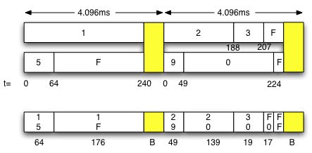
The routine is explained in the source code (nixie.asm), but a graphical representation can be seen above.
We can see that during the first refresh period, pair 0 is displayed. The tubes must display "15", then "1F" (F means "tube off"). We can easily see that "1" is displayed during the whole period (except blanking, represented in yellow in the picture) because tube 1 must display "1" as main digit, fading is 0, and brightness is 15. The 2nd tube of the pair is showing "5" for some period of time, then it is turned off. The reason is that tube 3 must display "5", fading is 0, but brightness is only 4.
Let's look at the second pair now. We see in the picture that the display will be "29", "20", "30", "F0" and finally "FF". We can explain this by looking at the parameters : tube 2 must display "2" faded with "3" (fading is 5, so "2" is shown longer than "3"). Brightness of this tube is 13, so the tube is turned off a little before the blanking period happens. Tube 4 must show "9" faded with "0", but fading is 25, so the alternate digit "0" is shown for a longer period of time. Brightness is 14, so the tube is also turned a little before the blanking period starts.
The list of event that is created by the routine, in this example, would be a byte array "15" 64 "1F" 176 "FF" 0 "29" 49 "20" 139 "30" 19 "F0" 17 "FF" 0, which can be interpreted as "show "15", after 64 timer 0 ticks, show "1F", after 176 ticks, do blanking, then show "29", after 49 ticks, show "20", etc..."
It is worth noting that building this list of events should be done only when a parameter has changed. If nothing has changed, the same sequence of events should be used to keep the display refreshed. (In the code, a flag is set when a parameter is changed, so that timer0's interrupt can rebuild the list only when necessary)
Conclusion: we have a very powerful routine here, which takes care of displaying 2 faded digits per tube, with individual tube brightness. And it only consumes one timer of the PIC!
Medium level
The medium level is where we update the parameters of the lowest level routine. The medium level routines are called every 64th second. At this level, each tube has again its set of parameters (refered as "auto_value", "auto_fading" and "auto_brightness" in the code). Let's quickly review each of these.auto_value
There are 2 such parameters for each tube : one to control the main digit, and one to control the alternate digit. The options are- do nothing : don't change the current value
- direct : the value (0-F) is directly given in the parameter.
- increment : add 1 to the current value (wrap to 0 after 9). Various speeds are possible (from 1/64s to 2s)
- decrement : same as above, but subtract 1
- random : set a random value. Again, various speeds are possible
- auto-set : set the value from a nibble in the clock structure. (Year, Month, Week, Hour, Minutes, Seconds,...) There are many possible values here, refer to the code for more information. For example, you can display the hours in 24-mode, or 12-mode, with or without leading zero, etc...
auto_brightness
One byte. Options are :- do nothing : keep the current setting
- direct (0-15)
- increment
- decrement
auto_fading
One byte. Options are :- no fading : main digit is always shown
- various fading types (some are generic and take parameters)
- direct value (0-31) : can be used to implement ghosting (for example, a ghost display of the seconds behind the minutes in a HH:MM clock)
Highest level
The highest level is where the clock is defined. This is a very powerful sequencer, where almost any set of actions can be triggered, on a quarter of a second precision! A sequencer is evaluated every quarter of a second, and eventual actions are triggered.The sequencer follows a program. Let's consider a very simple program, which implements a clock displaying HH:MM, with a type of fading, then display MM:DD during the 40 -> 50 seconds period. The clock should also turn itself off at 10pm, and come back at 6am. Let's implement this together!
The program always starts at the day_prog label. The day program can trigger actions based on the day of the week. In our example, the clock is doing the same thing every day, so we don't really need this functionnality. But we need at least one action for day_prog : we need to set the hourly program. Let's call this program hour_prog, so we have
day_prog
   ACTION	SUNDAY
     HOUR_PTR	hour_prog
   END_ACTION
   END_PROGRAM
Now, we need to define the hourly program. We need to turn the clock on at 6am, define the per-minute program, and turn if off at 10pm.
hour_prog
   ACTION	.0
     MINUTE_PTR	minute_prog
   END_ACTION
   ACTION	.6
     SET_POWER_ON
   END_ACTION
   ACTION	.22
     SET_POWER_OFF
   END_ACTION
   END_PROGRAM
Notice that the program uses 24 hours format. Please also note that the actions must be sorted in ascending time. Now we can define the per-minute program, named minute_prog here. This one is very simple, because we do the same thing every minute.
minute_prog
   ACTION	.0
     QSEC_PTR	qsec_prog
   END_ACTION
   END_PROGRAM
Now, let's define the per-quarter-of-a-second program, refered as qsec_prog here. The reader may ask why using a quarter of a second, instead of a second, and that's a good question. The answer is that we can do better looking effect if we have control every quarter of a second (think about scrolling the display, where one second is definitely too slow). Also, since we use a byte to code when the action should be triggered, quarters of second work well because 60 x 4 = 240, which fits in a byte.
qsec_prog
   ACTION	.0
     TUBE_BRIGHT	TUBE_ALL, DIRECT, 0xF
     TUBE_FADING	TUBE_ALL, FADING, 0x7
     HHMM
   END_ACTION
   EFFECT_TO_MMDD	.160, FADING_2
   EFFECT_TO_HHMM	.200, FADING_1
   END_ACTION
   END_PROGRAM
Note that the qsec_prog is using a few macros defined in effects.inc. For example, HHMM is really this :
     TUBE_VALUE		TUBE1, AUTO, HOURS_H
     TUBE_VALUE		TUBE2, AUTO, HOURS_L
     TUBE_VALUE		TUBE3, AUTO, MINUTES_H
     TUBE_VALUE		TUBE4, AUTO, MINUTES_L
     TUBE_VALUE		TUBE1_ALT, AUTO, HOURS_1_H
     TUBE_VALUE		TUBE2_ALT, AUTO, HOURS_1_L
     TUBE_VALUE		TUBE3_ALT, AUTO, MINUTES_1_H
     TUBE_VALUE		TUBE4_ALT, AUTO, MINUTES_1_L
We use the auto_value of the medium level routine. The main digits are auto set with the current time, and the alternate digits are set with the current time + 1 second. This gives the desired fading effect.
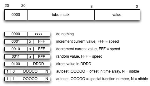
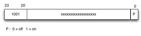
The following drawings explain how the bytecode is interpreted. Note that there is no need to use this directly, since macros are provided. Actually, the usage of macros is recommended, since it allows to change the various mappings without having to rewrite the program sequence : only the macros have to be adapted.
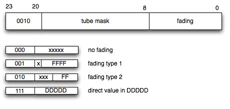
set value
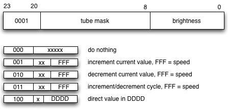
set brightness
set fading
set [day,hour,minute,qsec] ptr
When setting a pointer, up to 16 different pointers can be specified, and when the sequencer will trigger the action, a random number is generated and the pointer is chosen arbitrarily amongst the list. This allows the clock to behave in a non-predictable manner.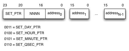
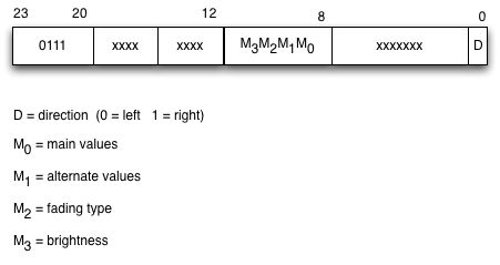
rotate
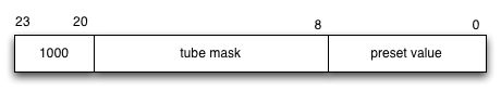
preset
power
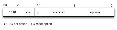
options