
High voltage generator
Generating 180V (or so) from a low voltage source (typically 9-18V) is actually pretty easy. All you need is a Boost converter, and some loop control. Microchip has an application note describing the problem and its solution. On the hardware side, we need a few components : an inductor, robust enough to pass the required current, a fast recovery diode, a high-voltage capacitor, and a high-voltage FET. Unless using some exotic (and expensive) FET, we also need a FET driver because the PIC PWM output is low-current 5V output, and that won't turn the FET ON and OFF properly. (FET drivers using individual components are described here). 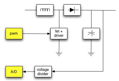
To minimise the ripple, we want to control the PWM as fast as we can, but we also don't want to overload the PIC with this job. The PIC timer has a nice feature, which is called "special event trigger". If programmed correctly, a timer (TIMER3 in our case) will trigger an event (starting an A/D conversion) without any software intervention! Once the A/D conversion is done, software will receive an interrupt from the A/D converter. Then, all we have to do is to adjust the PWM duty cycle, which only requires a few instructions. Therefore, we can afford to trigger an A/D conversion every 500us, and we will get a very nice and clean high voltage output. Also, we can minimize the inrush current by ramping the voltage when we turn the high-voltage generator. Another advantage of using the PIC to generate the high voltage is that we can change the output voltage programmatically.
Code snippet
The code is written in a very flexible manner: you define a few constants, and the code takes care of the rest for you. (Equations are coded in macros). In this first version, the input voltage is hardcoded, although it is possible to read the input voltage (the hardware has a voltage divider for this), and compute the various parameters based on it.XTAL_OSC EQU .32000000
;;;;;;;;;;;;;;;;;;;;;;;;;;;;;;;;;;;;;;;;;;;;;;;;;;;;;;;;;;;;;;;;;;;;;;;;;;;;;
; High Voltage generation
;;;;;;;;;;;;;;;;;;;;;;;;;;;;;;;;;;;;;;;;;;;;;;;;;;;;;;;;;;;;;;;;;;;;;;;;;;;;;
COIL EQU .330 ; in uH
COIL_AMP EQU .500 ; in mA
VIN EQU .12 ; in V
VOUT EQU .170 ; in V
AD_EVERY_US EQU .500 ; sample High Voltage every x us.
; voltage divider (HV -> AD)
R1 EQU .220000
R2 EQU .3300
; Compute the threshold to compare with the A/D converter.
; We multiply by 1024 (10 bits AD), and scale with the voltage divider.
; Then we divide by the supply of the PIC. It is *not* 5V because there is
; a 1N4148 diode between VCC and VBAT, so we lose .6V. Finally, we divide
; by 4 to have a 8-bits value to compare against ADRESH.
VOUT_AD10 EQU ((VOUT*.1024*R2/(R1+R2))*.100)/.440
VOUT_AD8 EQU VOUT_AD10>>2
Tcharge EQU (COIL_AMP * COIL)/VIN ; in ns
Tfall EQU (COIL_AMP * COIL)/(VOUT-VIN) ; in ns
Tflow EQU Tcharge + Tfall
Period EQU .4*Tflow/.3 ; in ns
PWM_PRESCALE EQU .1
PWM_PR2 EQU (((XTAL_OSC/(.4000*PWM_PRESCALE))*Period)/.1000000)-.1
PWM_DUTY EQU (Tcharge*(XTAL_OSC/(.1000*PWM_PRESCALE)))/.1000000
INST_PER_MS EQU XTAL_OSC/.4000
INST_EVERY_AD EQU (INST_PER_MS*AD_EVERY_US)/.1000
T3PRESCALE EQU .1
T3VALUE EQU (INST_EVERY_AD/T3PRESCALE)